
My degree work at this moment.
+6
KoD
QuickSilver
Hanyuu
Chillz
DarkNess
SuomiKukka
10 posters
Page 1 of 1

My degree work at this moment.
![]() by SuomiKukka Tue Feb 09, 2010 12:04 pm
by SuomiKukka Tue Feb 09, 2010 12:04 pm
Ok this is what I have accomplished so far.
I have designed power amp circuits and build them, they are two (stereo) +50 0 -50 circuits with 100w output, overvoltage, short-circuit, overcurrent. 120w cooling refrigerant.
powersupply with primary coil 250Vac 1Afuse in and two secondary coils of 30-33Vac max 6A out. With short-cricuit protection and active cooling 20x20x10mm 16dB (This cools the whole casing 300x270x80mm) this supply runs the powerampcircuits.
secondary regulated powersupply in 250Vac 1Afuse in and 12Vdc 1A out, no passive cooling, but the sucked air due the fan runs the job for this. This power runs the passive preamp, that needs 12Vdc 300mA maximum. Signal outputs there are one golded stereo rca (Intergrated), assimilated (if spelled right) to phones output, so theres 2 outputs phones are constant output as long as power is on, but speakers can be turned off with switch or remote control. There are 2 inputs, for 2 devices, first is setted to suit PC connection and second is setted to suit any common known rca output devices. (PC is common device put in the order to get best possible sound with PC there is an control circuit to set up the current, voltage and signal perfect).
Volume is motorized and min to max volume timing is 13second and can be controlled with remote control also.
The amp has 5 switches all together, Channel 1, Channel 2, On/Off for the whole intergrated amplifier, volume, and on/off speaker.
secondary powersupply is assimilated to control 2 devices, preamp and lights, (LED), Lighting circuit has Microcontroller coded by me, and outputted to a LED-stripe it has 3 differend programs, to move the leds by volume, voltage, or to just loop this lame program I set in there, and one led to show when the whole amplifier is set on.
Everything so far is ready, Im missing this moment casing and theoretical part (Maximum of 15pages per device and recomended of 5pages per device so that means 10pages are average and 15 is sure gate to diploma in my case because if I pop this one with perfect results I have been promised one).
Devices there are poweramp (x2 but seen as one device), preamp, light controller, 1st supply, 2nd supply. So there is a heck load of writing and I have completed 4pages, in theory I should write 75pages but professor said that just unhumain, So 50 is enough, dont still think Ill stop concidering 75.
The amount isnt the mai thing its the quality.
When Im ready Ill be uploading some pics and maybe videos.
Only thing this project is lacking is DC protection for speakers, so always when you turn the device on you must make sure there is 0-volume, because the turn-on, shoots out a powerfull DC spike and they really can damage or destroy small speakers.
This circuit is a power amplifier circuit with input sensitivity 1Vrms,
input impedance 20kOhms
Frequency response 10 to 100kHz (+/- 1dB), and total
harmonic distortion 0.002%.
class AB design.
Power supply : Dual 50VDC.
preamp:
inputs: 2 (line level)
output: 1 (line level)
input impedance: 5Kohm
output impedance: < 2.5Kohm
volume control speed: 13s typ. (0 to max. volume)
power supply: 12VDC / 300mA
dimensions: 235 x 165 x 47mm
remote control:
433MHz operation
approved design (report BLC/96-0452 according to I-ETS 300 220)
dimensions: 39 x 15 x 57mm

Everything from point A to B, are designed and build by me there have not been used 3rd party kits.
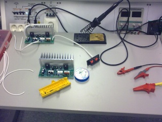
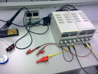 Test phase of amp circuits
I have designed power amp circuits and build them, they are two (stereo) +50 0 -50 circuits with 100w output, overvoltage, short-circuit, overcurrent. 120w cooling refrigerant.
powersupply with primary coil 250Vac 1Afuse in and two secondary coils of 30-33Vac max 6A out. With short-cricuit protection and active cooling 20x20x10mm 16dB (This cools the whole casing 300x270x80mm) this supply runs the powerampcircuits.
secondary regulated powersupply in 250Vac 1Afuse in and 12Vdc 1A out, no passive cooling, but the sucked air due the fan runs the job for this. This power runs the passive preamp, that needs 12Vdc 300mA maximum. Signal outputs there are one golded stereo rca (Intergrated), assimilated (if spelled right) to phones output, so theres 2 outputs phones are constant output as long as power is on, but speakers can be turned off with switch or remote control. There are 2 inputs, for 2 devices, first is setted to suit PC connection and second is setted to suit any common known rca output devices. (PC is common device put in the order to get best possible sound with PC there is an control circuit to set up the current, voltage and signal perfect).
Volume is motorized and min to max volume timing is 13second and can be controlled with remote control also.
The amp has 5 switches all together, Channel 1, Channel 2, On/Off for the whole intergrated amplifier, volume, and on/off speaker.
secondary powersupply is assimilated to control 2 devices, preamp and lights, (LED), Lighting circuit has Microcontroller coded by me, and outputted to a LED-stripe it has 3 differend programs, to move the leds by volume, voltage, or to just loop this lame program I set in there, and one led to show when the whole amplifier is set on.
Everything so far is ready, Im missing this moment casing and theoretical part (Maximum of 15pages per device and recomended of 5pages per device so that means 10pages are average and 15 is sure gate to diploma in my case because if I pop this one with perfect results I have been promised one).
Devices there are poweramp (x2 but seen as one device), preamp, light controller, 1st supply, 2nd supply. So there is a heck load of writing and I have completed 4pages, in theory I should write 75pages but professor said that just unhumain, So 50 is enough, dont still think Ill stop concidering 75.
The amount isnt the mai thing its the quality.
When Im ready Ill be uploading some pics and maybe videos.
Only thing this project is lacking is DC protection for speakers, so always when you turn the device on you must make sure there is 0-volume, because the turn-on, shoots out a powerfull DC spike and they really can damage or destroy small speakers.
This circuit is a power amplifier circuit with input sensitivity 1Vrms,
input impedance 20kOhms
Frequency response 10 to 100kHz (+/- 1dB), and total
harmonic distortion 0.002%.
class AB design.
Power supply : Dual 50VDC.
preamp:
inputs: 2 (line level)
output: 1 (line level)
input impedance: 5Kohm
output impedance: < 2.5Kohm
volume control speed: 13s typ. (0 to max. volume)
power supply: 12VDC / 300mA
dimensions: 235 x 165 x 47mm
remote control:
433MHz operation
approved design (report BLC/96-0452 according to I-ETS 300 220)
dimensions: 39 x 15 x 57mm
Everything from point A to B, are designed and build by me there have not been used 3rd party kits.
Test phase of amp circuits
SuomiKukka- Admin

-
 Number of posts : 1095
Age : 2023
Birthday : 2001-01-01
Registration date : 2009-06-15
Re: My degree work at this moment.
![]() by DarkNess Tue Feb 09, 2010 12:35 pm
by DarkNess Tue Feb 09, 2010 12:35 pm
Is this for your study or work or just for fun suv?

DarkNess-
 Number of posts : 4591
Age : 29
Birthday : 1994-07-24
Location : Holland
Job/hobbies : This is Serious.
Registration date : 2009-06-23
Re: My degree work at this moment.
![]() by Chillz Tue Feb 09, 2010 12:38 pm
by Chillz Tue Feb 09, 2010 12:38 pm
Yes ,why not. please stop spamming topics that doesnt belong to Spam. Thank you. Back on topic..paul_boy15 wrote:wait wait wait , should we care about u and ur life? :S...

Chillz- nD* Jail Member

- Number of posts : 2114
Age : 28
Birthday : 1995-10-16
Location : Sweden, Stockholm
Registration date : 2009-09-26
Re: My degree work at this moment.
![]() by Hanyuu Tue Feb 09, 2010 12:39 pm
by Hanyuu Tue Feb 09, 2010 12:39 pm
*nods head and give thumbs up*
( ̄∀ ̄)b
Though I have hardly any clue about those stuff as it is out of my league xD (<- business major )
)
Keep up the work desu~ (๑→ܫ←๑)
( ̄∀ ̄)b
Though I have hardly any clue about those stuff as it is out of my league xD (<- business major
)Keep up the work desu~ (๑→ܫ←๑)

Hanyuu- nD* Fun Member
- Number of posts : 1790
Age : 40
Birthday : 1983-10-13
Location : United States
Job/hobbies : College Student, Soccer, Drawing, Karaoking, Anime+Manga, Swimming
Registration date : 2009-07-25 -

Re: My degree work at this moment.
![]() by QuickSilver Tue Feb 09, 2010 12:48 pm
by QuickSilver Tue Feb 09, 2010 12:48 pm
|SuvI| wrote:I have designed power amp circuits and build them, they are two (stereo) +50 0 -50 circuits with 100w output, overvoltage, short-circuit, overcurrent. 120w cooling refrigerant.
powersupply with primary coil 250Vac 1Afuse in and two secondary coils of 30-33Vac max 6A out. With short-cricuit protection and active cooling 20x20x10mm 16dB (This cools the whole casing 300x270x80mm) this supply runs the powerampcircuits.
secondary regulated powersupply in 250Vac 1Afuse in and 12Vdc 1A out, no passive cooling, but the sucked air due the fan runs the job for this. This power runs the passive preamp, that needs 12Vdc 300mA maximum. Signal outputs there are one golded stereo rca (Intergrated), assimilated (if spelled right) to phones output, so theres 2 outputs phones are constant output as long as power is on, but speakers can be turned off with switch or remote control. There are 2 inputs, for 2 devices, first is setted to suit PC connection and second is setted to suit any common known rca output devices. (PC is common device put in the order to get best possible sound with PC there is an control circuit to set up the current, voltage and signal perfect).
Volume is motorized and min to max volume timing is 13second and can be controlled with remote control also.
The amp has 5 switches all together, Channel 1, Channel 2, On/Off for the whole intergrated amplifier, volume, and on/off speaker.
secondary powersupply is assimilated to control 2 devices, preamp and lights, (LED), Lighting circuit has Microcontroller coded by me, and outputted to a LED-stripe it has 3 differend programs, to move the leds by volume, voltage, or to just loop this lame program I set in there, and one led to show when the whole amplifier is set on.
Everything so far is ready, Im missing this moment casing and theoretical part (Maximum of 15pages per device and recomended of 5pages per device so that means 10pages are average and 15 is sure gate to diploma in my case because if I pop this one with perfect results I have been promised one).
Devices there are poweramp (x2 but seen as one device), preamp, light controller, 1st supply, 2nd supply. So there is a heck load of writing and I have completed 4pages, in theory I should write 75pages but professor said that just unhumain, So 50 is enough, dont still think Ill stop concidering 75.
The amount isnt the mai thing its the quality.
When Im ready Ill be uploading some pics and maybe videos.
Only thing this project is lacking is DC protection for speakers, so always when you turn the device on you must make sure there is 0-volume, because the turn-on, shoots out a powerfull DC spike and they really can damage or destroy small speakers.
This circuit is a power amplifier circuit with input sensitivity 1Vrms,
input impedance 20kOhms
Frequency response 10 to 100kHz (+/- 1dB), and total
harmonic distortion 0.002%.
class AB design.
Power supply : Dual 50VDC.
preamp:
inputs: 2 (line level)
output: 1 (line level)
input impedance: 5Kohm
output impedance: < 2.5Kohm
volume control speed: 13s typ. (0 to max. volume)
power supply: 12VDC / 300mA
dimensions: 235 x 165 x 47mm
remote control:
433MHz operation
approved design (report BLC/96-0452 according to I-ETS 300 220)
dimensions: 39 x 15 x 57mm
Everything from point A to B, are designed and build by me there have not been used 3rd party kits.
You lost me already at the first sentence haha
But it looks impressive Suvi, so keep up the good work!

QuickSilver- Admin
- Number of posts : 2691
Age : 67
Birthday : 1957-02-06
Registration date : 2009-09-23
Re: My degree work at this moment.
![]() by KoD Tue Feb 09, 2010 12:56 pm
by KoD Tue Feb 09, 2010 12:56 pm
paul_boy15 wrote:wait wait wait , should we care about u and ur life? :S...
dont read if you dont care, gtfo then.
Im gonna read it later cuz I found it intresting

KoD- nD* Fun Member
- Number of posts : 3513
Age : 31
Birthday : 1992-07-05
Location : weedcountry
Job/hobbies : follow fat guys with a tuba
Registration date : 2009-08-23
Re: My degree work at this moment.
![]() by Arnold Schwarzenegger Tue Feb 09, 2010 1:04 pm
by Arnold Schwarzenegger Tue Feb 09, 2010 1:04 pm
Awesome suvi  , post more of your stuff. its interesting
, post more of your stuff. its interesting 
Arnold Schwarzenegger- Number of posts : 1340
Age : 33
Birthday : 1990-07-14
Location : The Hague, Netherlands
Job/hobbies : Building Computer Systems,Boxing,Fitness,Playing Videogames
Registration date : 2009-07-04
Re: My degree work at this moment.
![]() by Samstein Tue Feb 09, 2010 1:24 pm
by Samstein Tue Feb 09, 2010 1:24 pm
does this mean you can build a computer?

Samstein- Number of posts : 286
Age : 35
Birthday : 1988-06-07
Location : Sweden Gothenburg
Job/hobbies : Construction Worker, Games, GYM, Party
Registration date : 2009-03-09
Re: My degree work at this moment.
![]() by Spx. Tue Feb 09, 2010 1:54 pm
by Spx. Tue Feb 09, 2010 1:54 pm
I'm going to read it tomorrow, since I got confused at the first sentence already the same as QuickSilver did..  Need to take some time for it.
Need to take some time for it.
Spx.- Number of posts : 2072
Age : 28
Birthday : 1995-11-02
Location : Holland, Rotterdam~
Job/hobbies : Skating mountainbiking, snowboarding, outdoor sports =)
Registration date : 2009-07-15
Re: My degree work at this moment.
![]() by neondragon Tue Feb 09, 2010 8:08 pm
by neondragon Tue Feb 09, 2010 8:08 pm
Good work Suvi
Do you know what SNR your preamp/power-amp circuits produce? Did you program the microcontroller for the LED's using C? What microcontroller is it?
Fun stuff ^^ Stay focused and get it all written up
Do you know what SNR your preamp/power-amp circuits produce? Did you program the microcontroller for the LED's using C? What microcontroller is it?
Fun stuff ^^ Stay focused and get it all written up
neondragon- Forums Admin
- Number of posts : 332
Age : 37
Birthday : 1986-08-14
Registration date : 2009-02-22
Re: My degree work at this moment.
![]() by SuomiKukka Tue Feb 09, 2010 10:29 pm
by SuomiKukka Tue Feb 09, 2010 10:29 pm
Microcontroller is Atmel 8-bit processor and coding is by program called Flow-Code its a handy tool with graphs to show how the code is injected and done, no bits and pieces need to use, only hex and occasionally bit level and desimal (inpossible in the processor), but the program is an converter it converts the full program in to the cpu rom at bits.
Final calculations are included when the time is right for the testing phase.
It is hard to define signal level since the audio signals are constantly changing, but if its necessary for the theory to come across I see its important to calculate the ratio.
"edit": I test it with blank recording and oscillosscope should show the variations to the original signal, I just set A-channel to see output at CD players (Open it up, and set signal and ground before cables), and B-channel to see S1/S2 input to see differences (also inside, not in the cables)
SuomiKukka- Admin
- Number of posts : 1095
Age : 2023
Birthday : 2001-01-01
Registration date : 2009-06-15
Page 1 of 1
Permissions in this forum:
You cannot reply to topics in this forum|
|
|